Hey everyone, Jake here, and if you’ve ever dealt with digital transistors for industrial controls, aerospace, or consumer electronics, you know how big of a deal gain measurement is. As someone who’s spent the last 8 years sourcing and testing these bad boys for our team, I get it—too many folks either guess at gain or use outdated methods that give them garbage data, leading to circuits that underperform or fail early. Today, let’s break this down like we’re chatting over coffee, no jargon overload, and plenty of real-world context since I’m right in the supplier game. Digital Transistors
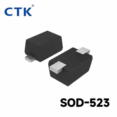
First off, let’s keep this super basic: digital transistors aren’t just like old-school BJTs you might’ve messed with in college labs. Digital ones are designed to switch fully on or off, but their “gain” here is a little different than the linear gain of analog transistors. Wait, let’s clarify that—when we talk about gain for digital devices, it’s the ratio of the output current when the transistor is fully on to the input current that switches it on. We call that DC current gain (hFE) for many, but there’s also a gain related to switching speed, which matters a ton for high-speed apps like 5G or motor drives. Messing up either one? You’re in for trouble. A few years back, we had a customer who ordered 10k digital transistors for their industrial motor controllers. They tested gain with a basic multimeter and thought everything was fine, but when they rolled them out, 12% failed within a month. Turned out they were measuring static gain at 25°C, but their motors were running at 75°C, where the actual gain dropped by 30%. That’s when I realized most DIY testers and even some small manufacturers skip the real-world variables.
So how do we actually measure this properly, no guesswork? Let’s start with the core setup you need—you can’t use your $20 multimeter for this. You need a few key tools: a precision DC power supply, a function generator or digital signal generator to give the input signal (the base current, basically), two accurate multimeters (or a data logger—way better for tracking changes over time), and a temperature-controlled test chamber, especially if you’re testing for extreme environments. Oh, and a load resistor for the output side—don’t skip that, because the output current is what the transistor is actually driving in your circuit.
Let’s walk through the step-by-step method that we use in our in-house test lab, the same one we share with our top aerospace clients. First, set up the test circuit. For a standard N-channel digital transistor (super common for most apps), you connect the collector (output) to the positive terminal of your power supply, with a load resistor between the collector and ground. The emitter goes straight to ground. Then, the base (input) of the transistor connects to your function generator, which will deliver a controlled input current. Wait—you need to set the input current precisely, not just a voltage. Digital transistors are current-driven, so if you use a fixed voltage, the input current will vary between units, messing up your gain reading. That’s a common mistake!
Next, set your test conditions. This is where a lot of people cut corners. Temperature is huge—if your transistor is going to work in a freezer or a factory that hits 90°F, test it there, not just at room temp. Voltage level matters too: most digital transistors are rated for 5V or 3.3V logic inputs, so you need to test at the exact operating voltage your customer will use. We usually test at three points: 25°C (room temp), the min operating temp (-40°C for automotive stuff), and the max operating temp (125°C for aerospace). That way, you know gain won’t spike or drop when the unit is in use.
Now the actual measurement part. First, measure the input base current (let’s call that Ib for short). That’s the current flowing into the base from your function generator—you can read that on your multimeter connected in series with the base. Then, switch the transistor fully on (that’s when the input signal is high, right?) and measure the collector current (Ic), that’s the current flowing through the collector and load resistor, also read on your second multimeter. Gain here is just Ic divided by Ib—simple math. But wait, there’s a catch: make sure the transistor is truly fully on, not in the linear region. How do you check that? Measure the collector-emitter voltage (Vce) when it’s on. If Vce is below 0.2V for most small signal digital transistors, that means it’s in saturation, which is what you want for digital switching. If Vce is higher, you’re not getting full on-state, so your Ic reading is wrong—your gain will be artificially low. That’s exactly what happened to that motor controller customer I mentioned earlier; they didn’t check Vce, so their Ic numbers were off, leading to bad gain data.
But wait, there’s another type of gain we care about for digital transistors—small-signal gain, sometimes called transconductance gain, especially for high-frequency apps like RF switches or 5G antennas. That’s different from the DC saturation gain we just talked about. Small-signal gain is the ratio of the change in output current to the change in input current at a specific frequency. To measure that, you’ll need an AC signal generator instead of DC, and an oscilloscope to track the input and output waveforms. For this, we use a vector network analyzer (VNA) for high-precision, but if you’re a smaller outfit, a good oscilloscope with current probes works for mid-frequency apps. This is critical for fast-switching circuits—if your small-signal gain drops at 100MHz, your digital transistor won’t switch fast enough, leading to signal distortion or overheating.
Now, let’s talk about common mistakes that even experienced people make. First, using a load resistor that’s too big. If your load resistor is too high, the collector current will be limited by the resistor, not the transistor, so Ic will be lower than it should be, making your gain calculation wrong. We always match the load to the transistor’s rated collector current—if a transistor is rated for 1A max, use a load that can handle at least 1.2A, and calculate the resistor value so that at full on-state, the voltage drop across the load plus Vce is equal to your power supply voltage. Another mistake is ignoring hysteresis. Digital transistors have a turn-on threshold and a turn-off threshold, so if your input signal is too slow, you might measure gain during the transition instead of the fully on state. We always use a square wave input with a rise time under 1 microsecond to avoid that.
What about when you’re testing mass-produced transistors, not just sample units? For high-volume orders like 100k units, you can’t test every single one in a temperature chamber—it’d be way too slow and expensive. So we use a production test fixture that has a socket for the digital transistors, automated power supplies, and a data logger that runs 100 units at a time, testing gain at room temp first. Any unit that falls outside our specified gain range (we give clients a tolerance, like ±10% of rated gain) gets flagged, and we pull those aside for re-testing at temperature. That’s how we keep our defect rate under 0.5%, which is way lower than the industry average—we take that seriously.
Also, let’s touch on spec sheet vs. real-world gain. A lot of companies just go by the gain number on the datasheet, but that’s usually a typical value, not a minimum or maximum. When we supply transistors, we give both a typical gain and a minimum gain, so our customers know that even the worst unit will perform to spec. For example, a standard small-signal digital transistor might have a typical gain of 200, but a minimum gain of 150. That means if you measure a unit with gain 160, it’s good, but 120, it’s defective. We test all our units to hit that minimum, so our clients don’t have to worry about underperforming parts.
Wait, another thing: gain drift over time. Digital transistors, like all semiconductors, can have gain change as they age, especially if they’re running at high temperatures or high currents. We do aging tests—bake the transistors at 150°C for 1000 hours, then re-test gain—to make sure it stays within spec. That’s a step most small suppliers skip, but it’s why our clients come back to us. They don’t want to replace parts 6 months down the line because gain dropped.
Let me give a quick example to make this concrete. Last quarter, we had a customer making LED flashlights for outdoor use. They were using a cheap transistor from a overseas supplier, kept having problems where some flashlights wouldn’t turn on at cold temperatures. They sent us samples, we tested their method vs. ours. They were measuring gain at 25°C, using a multimeter to estimate Ib, and their gain was fine. When we tested at -40°C, their gain dropped 40%, so the base current wasn’t enough to fully switch the transistor on, so the LED was too dim or wouldn’t turn on. We swapped them for our parts, which are tested at all temps, and their defect rate went from 8% to 0.2%. That’s the difference between proper gain measurement and cutting corners.
Now, if you’re a small business or hobbyist just testing a few prototypes, you don’t need a full temperature chamber or a VNA. You can start with a simple test setup: a bench power supply, a function generator, two multimeters, and a load resistor rated for your transistor’s max current. Just remember to test at your operating voltage, check that Vce is under 0.2V when on, and measure Ib precisely, not just voltage. For small-signal gain, you can use a signal generator at a low frequency (1kHz) and an oscilloscope to measure the output amplitude, that’ll give you a rough estimate of small-signal gain for prototyping.
But if you’re ordering digital transistors for actual production, don’t rely on cheap test methods. Ask your supplier what their gain testing process is. Do they test at temperature? Do they have minimum gain specs, not just typical? Do they test mass-produced units, not just samples? We answer all those questions honestly—we’ll send over our test reports for any order, no hoops to jump through. If you’re tired of defective transistors that cause circuit failures, let’s chat. We can talk about your specific application, what gain you need, and make sure you get parts that perform exactly as promised.
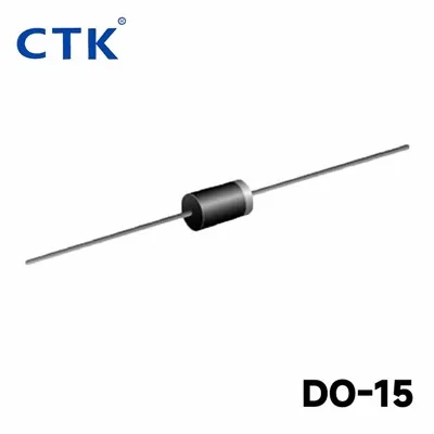
At the end of the day, measuring digital transistor gain isn’t rocket science, but it’s not guessing either. It’s about using the right tools, testing in real-world conditions, and not cutting corners. As a supplier, our job isn’t just to sell parts—it’s to make sure those parts work for you, wherever and however you use them. So if you need digital transistors, or you have questions about gain testing for your next project, reach out. We’re here to help.
Bidirectional Trigger Diode References
- Semiconductor Industry Association. (2022). Standard Test Methods for Bipolar Junction Transistors (BJTs) and Digital Transistors. JEDEC Publication JESD-87.
- Rashid, M. H. (2021). Power Electronics: Circuits, Devices, and Applications (4th ed.). Pearson Education.
- International Organization for Standardization. (2020). Space Grade Semiconductor Testing Standards for High-Reliability Applications. ISO 16750.
- Yang, S., et al. (2019). "Gain Characterization of High-Speed Digital Transistors for 5G RF Applications". IEEE Transactions on Electron Devices.
Tongke Electronic Co., Ltd
Tongke Electronic Co., Ltd. is one of the most experienced digital transistors manufacturers and suppliers in China, featured by quality products and low price. Please rest assured to wholesale advanced digital transistors made in China here from our factory. Contact us for pricelist.
Address: No.3,Chayuan Rd, Street 3, AilingKan, Dalingshan, Dongguan, Guangdong, China.
E-mail: jack@ctk-elec.com
WebSite: https://www.ctkchip.com/
